backup: Digital Circuit Course Design, Music Player with VGA Display
Busy with digital circuit labs. It’s been a long time since I coded QAQ. Nothing coded recently, so I just pull up the digital electricity course design QWQ~
Let’s start with a whole
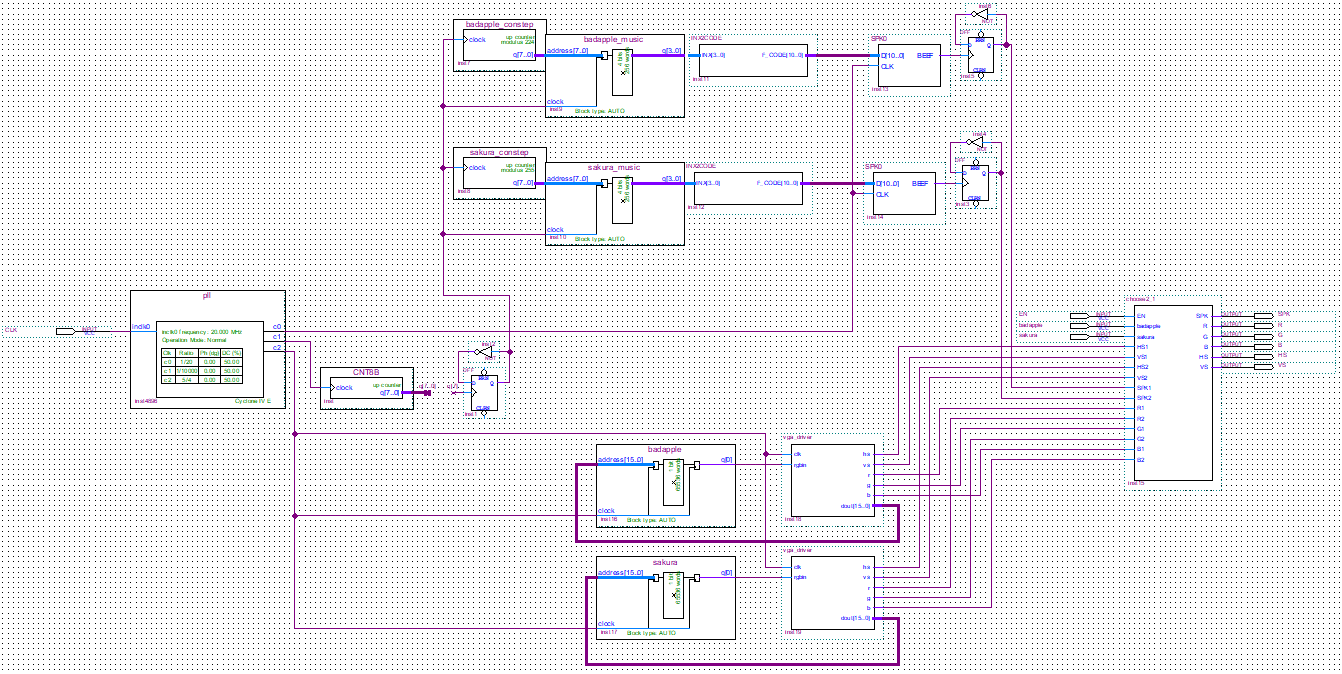
This is the top of the whole project, and then it is separate to each module
Phase-Locked Loop Crossover
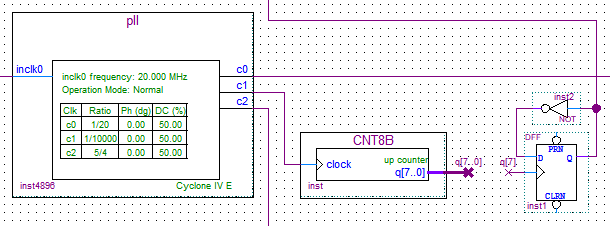
This Phase-Locked Loop is used for dividing the frequency. My FPGA board is a Cyclone IV and comes with a 20MHz clock signal. The buzzer needs 1MHz, the music needs 4KHz, and the VGA display 640 * 480 * 60Hz needs 25MHz
Music Module
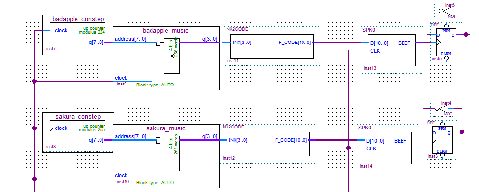
This is the music module, mainly divided into the number of notes recorded constep, recorded notes Rom, notes converted into buzzer frequency INX2CODE and sound SPK0
The constep is simply a counter that records the number of notes stored in the mif.
The ROM is needed to turn the score into a mif file and then use the ROM module to generate the device.
INX2CODE
1 | module INX2CODE (INX, F_CODE); |
SPK0

VGA Driver
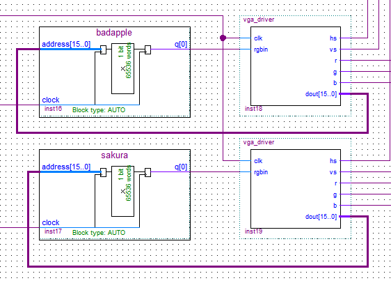
Convert the image to bmp format, then to mif, and save it to ROM like a note to generate a device.
vga_driver
1 | module vga_driver( |
Selector
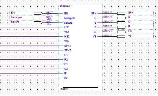
1 | module choose2_1( |
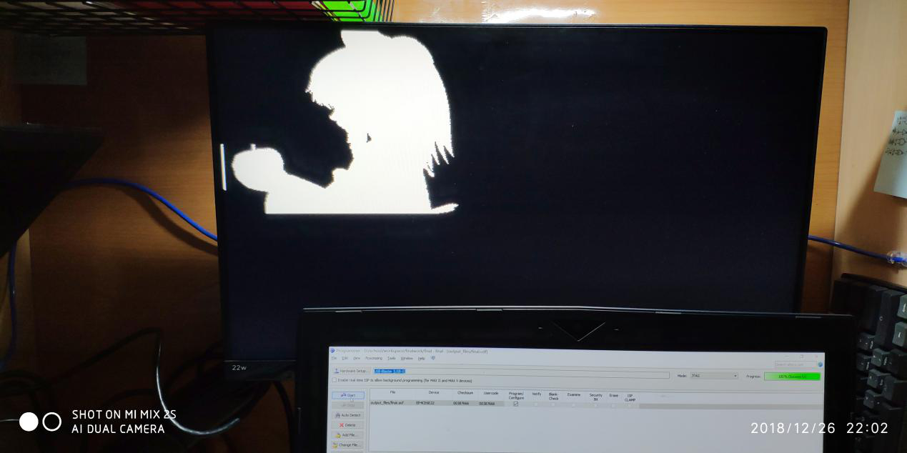
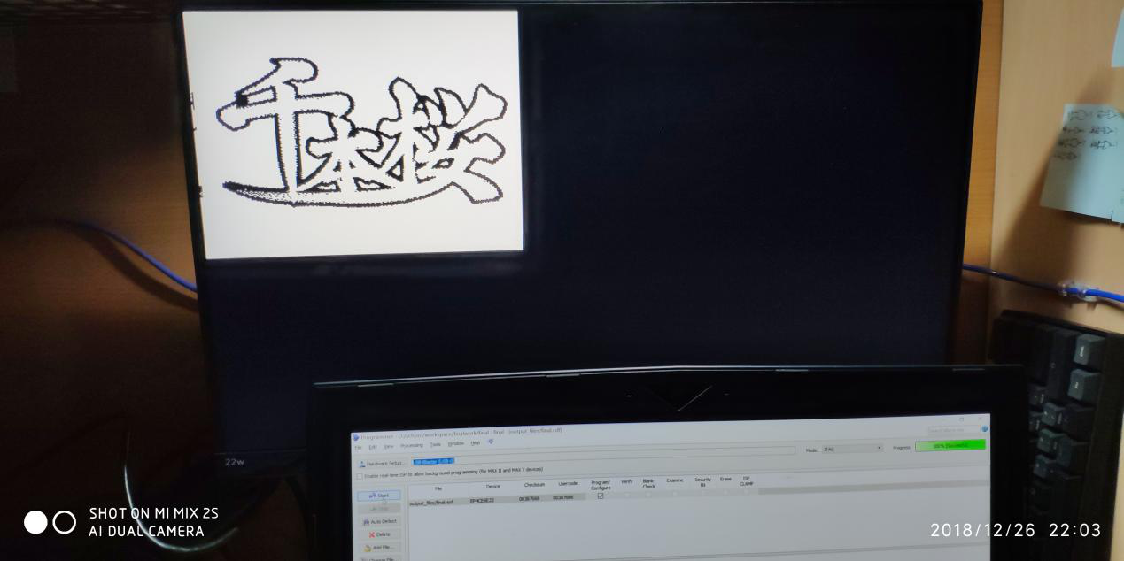
I do not have a VGA monitor can only go to a friend’s bedroom to play ~
Source code: Github
backup: Digital Circuit Course Design, Music Player with VGA Display
http://aslin.site/2022/03/09/backup-Digital-Circuit-Course-Design-Music-Player-with-VGA-Display/